In an InfoSWMM model, a Pump and Force Main system is a crucial part of the sewer network infrastructure. This system typically consists of the following components:
- Wet Well: This is a basin or tank where the inflow of sewage is collected. The physical parameters of the wet well, such as its dimensions and the levels at which the pumps start and stop, are significant to the model.
- Pump Type: InfoSWMM allows the user to define the type of pump used in the system. The pump type impacts the performance of the pumping station, including its flow rate and energy efficiency.
- Defined Pump Curve: The pump curve is a graph that describes the relationship between the head (pressure) that a pump can develop and the flow rate that it can achieve. This curve is essential for determining the operational efficiency of the pump under different conditions.
- Downstream Pressure Node: This is a point in the network where the pressure is measured after the pump. The pressure at this node can affect the performance of the pump and the flow in the force main.
- Downstream Force Main: This is a pipe that carries the wastewater under pressure from the pump to the next part of the sewer system. The characteristics of the force main, such as its length, diameter, and roughness, will influence the flow rate and pressure in the system.
As you can see, each component plays a critical role in the performance and efficiency of the Pump and Force Main system in the InfoSWMM model. Properly configuring these components in the model is key to accurately simulating the behavior of the real-world sewer system.
Step 1: Wet Well Data
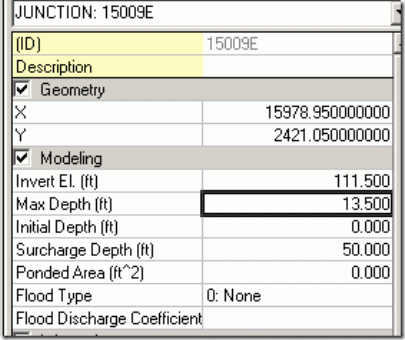
Enter the invert elevation, maximum depth of the Wet Well, the physical shape as either a function or shape table, and any evaporation or infiltration.
Step 2: Define the Pump Type
The Pump type is defined by a Pump Curve and the On and Off elevations:
The four types of pumps are:
- Volume - Flow
- Depth – Flow
- Head – Flow
- Depth - Flow
Step 3: Define the Pump Curve in the Operation Tab
Step 4: Set a Surcharge or Pressure Depth at the Downstream end of the Pump
Any positive Surcharge Depth in the Node will allow the program during the simulation to keep the node under pressure forcing flow through the Force Main.
Step 5: Force Main Data
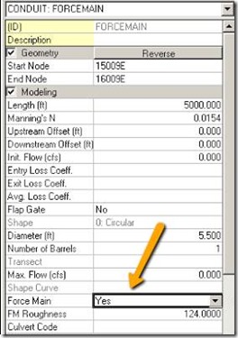
Define the downstream pipe(s) from the pump as Force Main conduits with either a Hazen Williams or Darcy-Weisbach coefficient (defined in the Run Manager of InfoSWMM)
Step 6: HGL Plot of the Force Main System
Step 7: Pump Summary in the RPT File


Leave a Reply