2.3.1 Flow Calculator (Simple in Innovyze H2OCalc)
The Flow Calculator category performs hydraulic calculations for the following elements: Circular Channel, Rectangular Channel, Triangular Channel, Trapezoidal Channel, Irregular Channel, and Pressurized Pipe.
Circular Channel
The circular channel dialog box is shown below.

Input for circular channel:
- Flow Unit – Select the desired flow unit.
- Head Loss Equation – Choose between the Manning, Kutter, Darcy-Weisbach (Colebrook-White) and Hazen-Williams friction loss calculation methods.
- Solving Target – Select the hydraulic parameter to solve for.
- Coefficient – The channel roughness coefficient.
- Slope – Channel longitudinal slope.
- Depth – Channel normal depth.
- Diameter – Circular channel inside diameter.
Output for circular channel:
- Flow Area – Flow cross-sectional area.
- Wetted Perimeter – Channel wetted perimeter.
- Hydraulic Radius – Flow area divided by the wetted perimeter.
- Velocity – Flow velocity.
- Velocity Head – Energy of flow velocity.
- Top Width – Length of free top water surface (zero for full flow condition).
- Critical Depth – Depth of water under minimum specific energy.
- Critical Slope – Channel slope under critical depth.
- Specific Energy – Velocity head plus pressure head.
- Froude Number – Flow characteristics dimensionless parameter.
- Flow Type – Subcritical or supercritical flow characteristics in channel.
- Percent Full – Percentage of actual channel flow depth based on full flow.
- Full Discharge – Channel flow rate when flowing full.
- Full Slope – Channel slope under full flow.
- Maximum Discharge – Flow rate when flow depth equals 0.938 times circular channel diameter (applies only to circular channel).
- Discharge (Q) – Uniform channel flow rate.
Rectangular Channel
The rectangular channel dialog box is shown below.
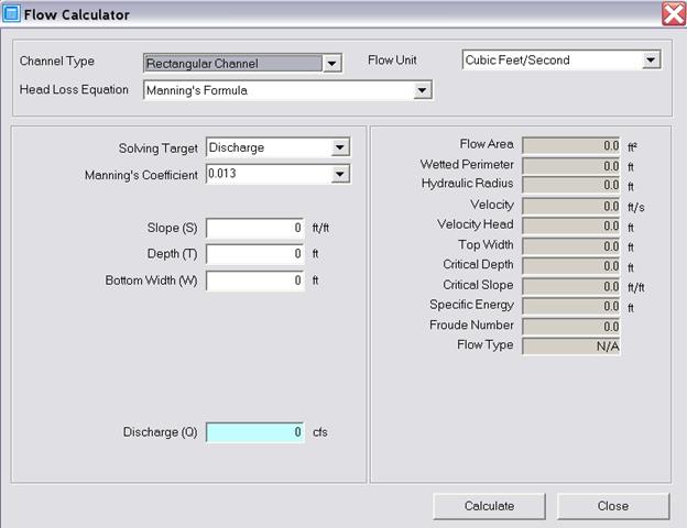
Input for rectangular channel:
- Flow Unit – Select the desired flow unit.
- Head Loss Equation – Choose between the Manning, Kutter, Darcy-Weisbach (Colebrook-White) and Hazen-Williams friction loss calculation methods.
- Solving Target – Select the hydraulic parameter to solve for.
- Coefficient – The channel roughness coefficient.
- Slope – Channel longitudinal slope.
- Depth – Channel normal depth.
- Bottom Width – Width of the channel.
Output for rectangular channel:
- Flow Area – Wetted area.
- Wetted Perimeter – Channel wetted perimeter.
- Hydraulic Radius – Flow area divided by the wetted perimeter.
- Velocity – Flow velocity.
- Velocity Head – Energy of flow velocity.
- Top Width – Length of free top water surface (same as bottom width at all depths).
- Critical Depth – Depth of water under minimum specific energy.
- Critical Slope – Channel slope under critical depth.
- Specific Energy – Velocity head plus pressure head.
- Froude Number – Flow characteristics dimensionless parameter.
- Flow Type – Subcritical or supercritical flow characteristics in channel.
- Discharge (Q) – Uniform channel flow rate.
Triangular Channel
The triangular channel dialog box is shown below.
Input for triangular channel:
- Flow Unit – Select the desired flow unit.
- Head Loss Equation – Choose between the Manning, Kutter, Darcy-Weisbach (Colebrook-White) and Hazen-Williams friction loss calculation methods.
- Solving Target – Select the hydraulic parameter to solve for.
- Coefficient – The channel roughness coefficient.
- Slope – Channel longitudinal slope.
- Depth – Channel normal depth.
- Left Side Slope – Horizontal increase in channel width per unit increase in depth (H: 1V) for the left side of the channel.
- Right Side Slope – Horizontal increase in channel width per unit increase in depth (H: 1V) for the right side of the channel.

Output for triangular channel:
- Flow Area – Wetted area.
- Wetted Perimeter – Channel wetted perimeter.
- Hydraulic Radius – Flow area divided by the wetted perimeter.
- Velocity – Flow velocity.
- Velocity Head – Energy of flow velocity.
- Top Width – Length of free top water surface.
- Critical Depth – Depth of water under minimum specific energy.
- Critical Slope – Channel slope under critical depth.
- Specific Energy – Velocity head plus pressure head.
- Froude Number – Flow characteristics dimensionless parameter.
- Flow Type – Subcritical or supercritical flow characteristics in channel.
- Discharge (Q) – Uniform channel flow rate.
Trapezoidal Channel
The trapezoidal channel dialog box is shown below.

Input for trapezoidal channel:
- Flow Unit – Select the desired flow unit.
- Head Loss Equation – Choose between the Manning, Kutter, Darcy-Weisbach (Colebrook-White) and Hazen-Williams friction loss calculation methods.
- Solving Target – Select the hydraulic parameter to solve for.
- Coefficient – The channel roughness coefficient.
- Slope – Channel longitudinal slope.
- Depth – Channel normal depth.
- Bottom Width – Bed width of the channel.
- Left Side Slope – Horizontal increase in channel width per unit increase in depth (H: 1V) for the left side of the channel.
- Right Side Slope – Horizontal increase in channel width per unit increase in depth (H: 1V) for the right side of the channel.
Output for trapezoidal channel:
- Flow Area – Wetted area.
- Wetted Perimeter – Channel wetted perimeter.
- Hydraulic Radius – Flow area divided by the wetted perimeter.
- Velocity – Flow velocity.
- Velocity Head – Energy of flow velocity.
- Top Width – Length of free top water surface.
- Critical Depth – Depth of water under minimum specific energy.
- Critical Slope – Channel slope under critical depth.
- Specific Energy – Velocity head plus pressure head.
- Froude Number – Flow characteristics dimensionless parameter.
- Flow Type – Subcritical or supercritical flow characteristics in channel.
- Discharge (Q) – Uniform channel flow rate.
Irregular Channel
The irregular channel dialog box is shown below.

Input for irregular channel:
- Flow Unit – Select the desired flow unit.
- Head Loss Equation – Choose between the Manning, Kutter, Darcy-Weisbach (Colebrook-White) and Hazen-Williams friction loss calculation methods.
- Solving Target – Select the hydraulic parameter to solve for.
- Slope – Channel longitudinal slope.
- Water Surface Elevation – Elevation corresponding to the water depth.
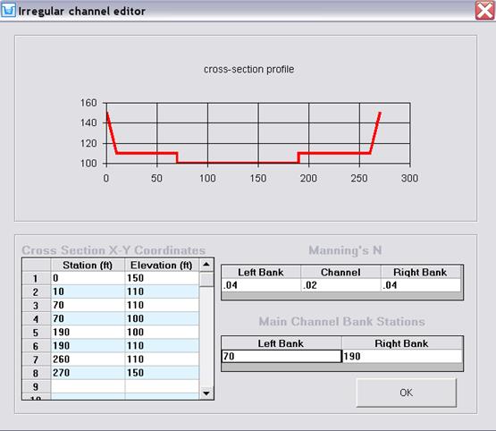
- Channel Cross Section – Station vs. Elevation data that represents shape of the channel. The Edit Section button initiates the irregular channel editor shown below.
- Left Bank Coefficient – Roughness coefficient for the left bank of the channel.
- Right Bank Coefficient – Roughness coefficient for the right bank of the channel.
- Channel Coefficient – Roughness coefficient for the main (center) channel.
- Main Channel Bank Stations – Stations at which the main channel ends and the banks start from either side of the channel (i.e., left and right).
Output for irregular channel:
- Flow Area – Wetted area.
- Wetted Perimeter – Channel wetted perimeter.
- Hydraulic Radius – Flow area divided by the wetted perimeter.
- Velocity – Flow velocity.
- Velocity Head – Energy of flow velocity.
- Top Width – Length of free top water surface.
- Critical Depth – Depth of water under minimum specific energy.
- Critical Slope – Channel slope under critical depth.
- Specific Energy – Velocity head plus pressure head.
- Froude Number – Flow characteristics dimensionless parameter.
- Flow Type – Subcritical or supercritical flow characteristics in channel.
- Depth – Flow depth.
- Elevation Range – Difference in elevations at the top and at the bottom of the channel.
- Discharge (Q) – Uniform channel flow rate.
The dialog box for irregular channel cross-section editor is shown below. The inputs are described above along with the irregular channels inputs.
Pressurized Pipe
The pressurized pipe calculator applies the energy equation between two points (points 1 and 2) and evaluates the outputs listed below. The pressurized pipe dialog box is shown below.
Input for pressurized pipe:
- Flow Unit – Select the desired flow unit.
- Head Loss Equation – Choose between the Manning, Kutter, Darcy-Weisbach (Colebrook-White) and Hazen-Williams friction loss calculation methods.
- Solving Target – Select the hydraulic parameter to solve for.
- Coefficient – The channel roughness coefficient.
- Diameter – Circular pipe diameter.
- Length – Pipe length.
- Pressure at 1– Pressure at the upstream end of the pipe.
- Pressure at 2– Pressure at the downstream end of the pipe.
- Elevation at 1– Elevation at the upstream end of the pipe.
- Elevation at 2– Elevation at the downstream end of the pipe.
Output for pressurized pipe:
- Flow Area – Wetted area.
- Wetted Perimeter – Channel wetted perimeter.
- Hydraulic Radius – Flow area divided by the wetted perimeter.
- Velocity – Flow velocity.
- Velocity Head – Energy of flow velocity.
- Head Loss – Energy loss due to friction.
- Energy Grade at 1 – Total energy head (i.e., sum of pressure head, velocity head, and elevation head) at the upstream end.
- Energy Grade at 2 – Total energy head (i.e., sum of pressure head, velocity head, and elevation head) at the downstream end.
- Hydraulic Grade at 1 – Sum of pressure head and elevation head at the upstream end.
- Hydraulic Grade at 2 – Sum of pressure head and elevation head at the upstream end.
- Friction Slope – Slope of the head loss due to friction between sections 1 and 2.
- Discharge (Q) – Pipe flow rate.


Leave a Reply