3.14 Water Hammer
Surge analysis is important to estimate the worst-case events in the Water Distribution Systems (WDS). Transient regimes in WDS are inevitable and will normally occur as a result of action at pump stations and control valves. Regions that are particularly susceptible to transients are high elevation areas, locations with either low or high static pressures, and regions far removed from overhead storage. They are generally characterized by fluctuating pressures and velocities and are critical precisely because pressure variations can be of high magnitude, possibly large enough to break or damage pipes or other equipment, or to greatly disrupt delivery conditions.
This section presents the calculation of potential surge using Joukowski equation, which is widely applied as a simplified surge analysis, and wave speed calculation. In the end, it provides the calculation of the inertia of pumps and motors, which are important for transients caused by pump failure.
Joukowski Expression
The pressure rise for instantaneous closure is directly proportional to the fluid velocity at cutoff and to the velocity of the predicted surge wave. Thus, the relationship used for analysis is simply the well-known Joukowski expression for sudden closures in frictionless pipes

where
![]() = surge pressure (m , ft)
= surge pressure (m , ft)
![]() = velocity change of water in the pipeline (m/s, ft/s)
= velocity change of water in the pipeline (m/s, ft/s)
c = wave speed (m/s, ft/s)
A = cross-sectional area (m2, ft2 h)
g = gravitational acceleration (9.81 m/s2, 32.17 ft/s2)
Wave Speed
The wave speed, c, is influenced by the elasticity of the pipe wall. For a pipe system with some degree of axial restraint a good approximation for the wave propagation speed is obtained using

where Ef = elastic modulus of the fluid (for water, 2.19 GN/m2, 0.05 Glb/ft2)
ρ = density of the fluid (for water, 998 kg/m3, 1.94 slug/ft3)
Ec = elastic modulus of the conduit (GN/m2, Glb/ft2)
D = pipe diameter (mm, inch)
t = pipe thickness (mm, inch)
KR = coefficient of restraint for longitudinal pipe movement.
The constant KR takes into account the type of support provided for the pipeline. Typically, three cases are recognized with KR defined for each as follows (m is the Poisson’s ratio for the pipe material):
Case a: The pipeline is anchored at the upstream end only.
KR = 1 - m / 2
Case b: The pipeline is anchored against longitudinal movement.
KR = 1 - m2
Case c: The pipeline has expansion joints throughout.
KR = 1
The following table provides physical properties of common pipe materials.
Table 3-8: Physical Properties of Common Pipe Materials
| Material | Young’s Modulus (Ec) | Poisson’s Ratio, μ | |
| GN/m2 | Glb/ft2 | ||
| Asbestos Cement | 23 - 24 | 0.53 - 0.55 | - |
| Cast Iron | 80 - 170 | 1.8 - 3.9 | 0.25 - 0.27 |
| Concrete | 14 - 30 | 0.32 - 0.68 | 0.1 - 0.15 |
| Reinforced Concrete | 30 - 60 | 0.68 - 1.4 | - |
| Ductile Iron | 172 | 3.93 | 0.3 |
| PVC | 2.4 - 3.5 | 0.055 - 0.08 | 0.46 |
| Steel | 200 - 207 | 4.57 - 4.73 | 0.30 |
Inertia of Pumps and Motors
The combined inertia of pumps and motors driving them, including the connecting shafts and couplings, is required for transient analysis associated with the starting and stopping of pumps. The equations provided below are intended to be used as an initial guide to the inertia values that may be used as a reasonable first approximation, when more accurate data is not available. The total inertia for the pump/motor unit is the sum of both pump and motor inertias. The following inertia calculations are based on Thorley (2004).
Pump Inertias
From the linear regression analysis of 300 pump inertia data, two equations were developed for predicting the inertia I of pump impellers, including the entrained water and the shaft on which the impeller is mounted. The first equation represents the upper set of the data, and applies to single- and double-entry impellers, single and multistage, and horizontal and vertical, spindle machines.
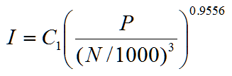
where I = pump inertia (kg m2, lb ft2)
C1 = coefficients (0.03768, 0.6674)
P = power (kW, hp)
N = pump speed (rev/min)
The second equation is for lower set of the data and represents relatively small, single-entry, radial flow impellers of lightweight design. This is applied to relatively small pumps of lightweight design.
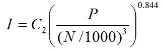
where C2 = coefficients (0.03407 in SI, 0.6244 in English)
Motor Inertias
Similar to pump inertia, linear regression of the motor inertia data yields the following equations.

where C3 = coefficients (0.0043 in SI, 0.0648 in English).

Leave a Reply