Pump Calculations for #InfoSWMM and #SWMM5
Introduction: H2OCalc is a hydrology and hydraulics calculator sold by Innovyze that has many of the equations and calculation methods used in InfoSWMM, ICM and SWMM5. This is the H2OCalc information for Pumps.
A Pump is used to augment head to the system (water distribution systems or waste water collection systems), and helps to lift water from low lying locations to a top of a hill or reservoir so that water could flow by gravity. The following figure shows an example pump configuration along with its corresponding energy and hydraulic grade lines (EGL and HGL).
Application of the energy equation between the water surfaces yields

where hp = head added by the pump (m, ft)
z = elevation with respect to a specified datum (m, ft)
hL = total head loss including friction and form losses (m, ft)
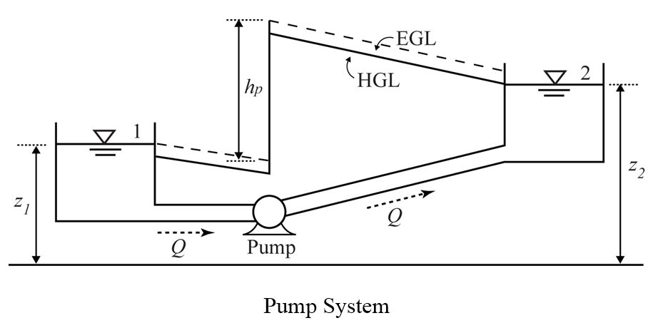
The term hp is more widely referred to as the system head, or total dynamic head, that must be overcome before fluid can be lifted by the pump. Since the magnitude of losses is directly proportional with the flow rate, Equation (17) indicates that for a given discharge, a unique system head is needed to maintain flow. The relationship is referred to as the system equation. Following, description of pump power calculation, pump characteristic curve, pump torque calculation and pump affinity laws is given.
Pump Power
The head supplied by a pump to the system can be converted to water power, or output power as follows.
where g = specific weight of water (9810 N/m3, 62.4 lb/ft3)
Q = pump discharge (m3/s, ft3/s)
hp = head added by the pump to the system (m, ft), see Equation (17)
Pwater = water power supplied by pump (KW, hp)
K = unit conversion factor (1000 in SI, 550 in English)
Water power will always be less than the power supplied to the pump shaft, often referred to as the brake power. Brake power is expressed as
where Pbrake = the power supplied to the pump (KW, hp)
![]() = the efficiency of the pump motor (the ratio of power supplied to the pump to the energy converted
= the efficiency of the pump motor (the ratio of power supplied to the pump to the energy converted
to actual power in the flow)
Pump Torque
The relationship between the water power supplied by a pump and the torque exerted by the impeller on the water is expressed as
where T = torque (KN-m, lbf-ft)
w = pump speed in RPM
K = constant (9.55 in SI, and 5252 in English)
Pump Specific Speed
Pump specific speed (Nsp) is a dimensionless parameter used for preliminary selection of the type of pump that is most appropriate for a given application. The specific speed is defined as
where N = pump speed (rpm)
Q = flow rate (m3/s, gpm)
H = pump head (m, ft)
Pump Characteristic Curve
Pump characteristic curves are usually presented graphically describing the relationship between pump head, hp, and the flow rate, Q using either an exponential equation or 3-point quadratic form. The exponential pump characteristic curve is given as
where hc = the pump cutoff head associated with the zero flow condition (m, ft)
Kp = resistance coefficient
b = flow exponent
nR = pump speed ratio (the ratio of the actual pump speed to the rated pump
speed); for constant speed pump operation, nR is equal to 1.
Given three hp-Q points [hc, (hp,1, Q1),
(hp,2, Q2)], the pump curve can be calculated as
If a single rated capacity (hrated, Qrated) is given, two more points can be added to the curve by assuming a shutoff head at zero flow equal to 133% of the design head and a maximum flow at zero head equal to twice the design flow. Then, the curve can be treated as a three-point curve.
The 3-point quadratic type of pump characteristic curve is

where ap, bp, cp are the coefficients of the quadratic curve.
The coefficients are calculated as
If pump are constructed from impellers and casings that are geometrically similar (same shape but scale to different size), their pump curves will vary in a predictable manner. Similarly, altering the motor speed that is driving a particular pump will also have a predictable effect. The so-called affinity or similarity laws describe the relationship between the pump flow, head, and motor speed. Knowledge of these relationships will accelerate selecting a pump/motor combination for a particular application.
where Q = pump flow (Length3/Time)
n = pump speed (1/Time)
hp = pump head (Length)
D = impeller diameter Length)
Using the above equations, variable speed pumps can be directly modeled by fixing the impeller diameter.
System Head Curve
The ability to determine system head curves (sometimes called head capacity curves) is an essential task in the design of pumping systems. These curves are useful in determining the rating of the pumps and in assessing the number of pumps required and the type of drive to be used. Each curve describes the relationship between system head and capacity under identified conditions. More specifically, the curve represents the variation in total dynamic head against which the pumps will be required to operate under various flow conditions. The intersection of the system head curve (the resistance the pump must overcome) and the pump characteristic curve (head developed by the pump as a function of capacity) defines the point at which the pump will operate (see Figure below).
The solution of the energy equation gives the system curve as:
where
![]() is the head loss in pipe 1,
is the head loss in pipe 1,
![]() is the head loss in pipe 2,
is the head loss in pipe 2,
![]() is the minor loss in pipe 1, and
is the minor loss in pipe 1, and
![]() is the minor loss in pipe 2.
is the minor loss in pipe 2.
If the Hazen-Williams head loss expression and English units are used, this gives:

where ![]()
is the sum of the minor loss coefficients in pipe i.