Creating a Unit Hydrograph in InfoSewer and H2OMap Sewer
To derive a storm Hydrograph, InfoSewerH20Map Sewer Pro. uses the Unit Hydrograph Theory. If a natural unit hydrograph (a unit hydrograph created from observed field data) is available for the watershed being investigated, the user may provide it in the form of a pattern. If a natural unit hydrograph does not exist,InfoSewerH20Map Sewer Pro. can generate a synthetic unit hydrograph using four different techniques (i.e., SCS dimensionless unit hydrograph, SCS triangular unit hydrograph, the tri-triangle method, or the Colorado Urban Hydrograph Procedure). Theoretical detail of the methods is available in Section 4.5.
In this section, you will create one natural unit hydrograph and one synthetic unit hydrograph using the tri-triangle method. Later in the tutorial, you will assign the natural unit hydrograph to some of the loading manholes in the “Tutorial” project. The synthetic unit hydrograph will be assigned to the remaining loading manholes.
Create a natural unit hydrograph using the following procedure:
· Select the OPERATION DATA tab ![]() from the CONTROL CENTER in H2OMap Sewer or the Operations Tab in the Attribute Browser of InfoSewer, select PATTERN and click on the “New” button
from the CONTROL CENTER in H2OMap Sewer or the Operations Tab in the Attribute Browser of InfoSewer, select PATTERN and click on the “New” button ![]() in the upper left-hand corner of the window.
in the upper left-hand corner of the window.
· You are then prompted to enter a new ID and description for the pattern. Enter “EXPLICIT, Natural Unit Hydrograph” in the PATTERN ID field and choose the “OK” button.
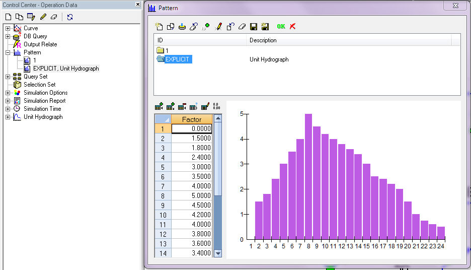
· The PATTERN dialog box now appears on the screen. You will enter the following 24 unit hydrograph ordinates. The pattern time step is assumed to be one hour. Please note that unlike the sanitary load patterns, the ordinates of unit hydrograph pattern represent actual storm flow values i.e., they are not multiplication factors.
· To define the values of the twenty-four ordinates for the unit hydrograph pattern, perform the following:
| Ordinate 1 | Ordinate 2 | Ordinate 3 | Ordinate 4 | Ordinate 5 | Ordinate 6 |
| 0.0 | 1.5 | 1.8 | 2.4 | 3.0 | 3.5 |
| Ordinate 7 | Ordinate 8 | Ordinate 9 | Ordinate 10 | Ordinate 11 | Ordinate 12 |
| 4.0 | 5.0 | 4.5 | 4.2 | 4.0 | 3.8 |
| Ordinate 13 | Ordinate 14 | Ordinate 15 | Ordinate 16 | Ordinate 17 | Ordinate 18 |
| 3.6 | 3.4 | 3.0 | 2.5 | 2.4 | 2.2 |
| Ordinate 19 | Ordinate 20 | Ordinate 21 | Ordinate 22 | Ordinate 23 | Ordinate 24 |
| 2.0 | 1.5 | 1.0 | 0.75 | 0.6 | 0.5 |
· Choose the “Set Rows” button ![]() , enter “24” as the value, and choose “OK”.
, enter “24” as the value, and choose “OK”.
· Enter values of the ordinates as defined above and press the ENTER key to apply the change. As you add the values the graph will be automatically updated on the dialog box.
· Click on the “Save” button ![]() at the top of the dialog box to apply the changes to the pattern.
at the top of the dialog box to apply the changes to the pattern.
· Choose the “OK” button ![]() to close the PATTERN dialog box. Now you have created the pattern. The following picture illustrates how the pattern should appear on the screen.
to close the PATTERN dialog box. Now you have created the pattern. The following picture illustrates how the pattern should appear on the screen.
Next, you will define this pattern as a natural unit hydrograph in H2OMAP Sewer/Pro.
· 1. Select the OPERATION DATA tab ![]() from the CONTROL CENTER or the Operations Tab in the Attribute Browser of InfoSewer. select UNIT HYDROGRAPH and click on the “New” button
from the CONTROL CENTER or the Operations Tab in the Attribute Browser of InfoSewer. select UNIT HYDROGRAPH and click on the “New” button ![]() in the upper left-hand corner of the window.
in the upper left-hand corner of the window.
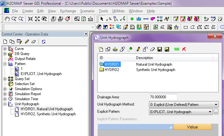
· 2. You are then prompted to enter a new ID and description for the hydrograph. Enter “HYDRO1, Natural Unit Hydrograph” in the NEW ID field and choose the “OK” button. The UNIT HYDROGRAPH dialog box should appear on the screen.
· 3. Enter “70” in the DRAINAGE AREA field. This refers to the area of the subwatersheds that drain to the location where the unit hydrograph is derived. The unit is in acres if US Customary Units are used, and is in square meters for SI Units.
· 4. Select the EXPLICIT option for the UNIT HYDROGRAPH PATTERN TYPE. Unit hydrographs provided by the user are EXPLICIT unit hydrographs. Implicit unit hydrographs refer to those internally generated by the model. Click on the EXPLICIT PATTERN drop down box, and select “EXPLICIT, Natural Unit Hydrograph” pattern.
· 5. Click on the “Save” button ![]() at the top of the dialog box to apply the changes. The following picture illustrates how the UNIT HYDROGRAPHdialog box should appear on the screen.
at the top of the dialog box to apply the changes. The following picture illustrates how the UNIT HYDROGRAPHdialog box should appear on the screen.
· 6. Choose the “OK” button ![]() to close the UNIT HYDROGRAPH dialog box.
to close the UNIT HYDROGRAPH dialog box.
Next, you will assign the data required to create an Implicit unit hydrograph using the tri-triangle method as follows:
· Select the OPERATION DATA tab from the CONTROL CENTER, select UNIT HYDROGRAPH and click on the “New” button in the upper left-hand corner of the window. Enter “HYDRO2, Synthetic Unit Hydrograph” in the NEW ID field and choose the “OK” button. The UNIT HYDROGRAPH dialog box should appear on the screen.
· Enter “50” in the DRAINAGE AREA field. Select the IMPLICIT option in the UNIT HYDROGRAPH PATTERN TYPE, and enter the values given below for the nine parameters of the tri-triangle method.
| Tri-Triangle Parameters | Value |
| R: Effective Rainfall Volume (%) | 60.000 |
| R1: Triangle1 Rainfall Volume (%) | 40.000 |
| R2: Triangle2 Rainfall Volume (%) | 40.000 |
| T1: Time to Peak 1 (hr) | 2.000 |
| T2: Time to Peak 2 (hr) | 6.0000 |
| T3: Time to Peak 3 (hr) | 8.0000 |
| K1: Recession Constant1 | 2.0000 |
| K2: Recession Constant2 | 3.0000 |
| K3: Recession Constant3 | 3.0000 |
· Click on the “Save” button at the top of the dialog box to apply the changes. The following picture illustrates how the UNIT HYDROGRAPH dialog box should appear on the screen.
· 
· Choose the “OK” button ![]() to close the UNIT HYDROGRAPH dialog box.
to close the UNIT HYDROGRAPH dialog box.
We have created one explicit unit hydrograph and one implicit unit hydrograph. Next, we will create analysis rainfall data.