Infiltration Trench LID Control for #LID’s in #SWMM5 and #InfoSWMM
This is an introduction along with images of the LID Control and data require3ments in InfoSWMM. Every InfoSWMM Control uses from one to 5 layers of data - each with different data requirements. You can use the Siting Manger of InfoSWMM Sustain to find LID locations and the LID Optimizer to find the optimized number of units, cost of units, area and thickness of the LID layers based on your runoff and water quality control objectives.
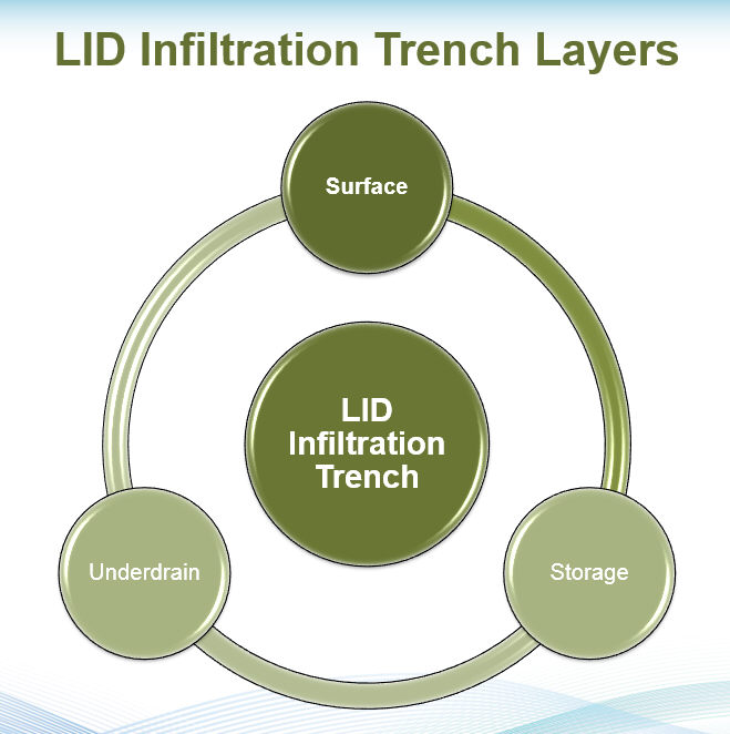
The Infiltration Trench LID Control has three components or Process Layers: Surface, Storage and Underdrain.
The Surface Process Layer consists of:
· The Storage Depth in inches or millimeters
· The Vegatative Cover Fraction (0 to 1),
· Surface Roughness (Manning’s n)
· Surface Slope (percent).


The Storage Process Layer consists of:
· The Storage Height in inches or millimeters,
· The Void Ratio as a Fraction (0 to 1),
· Surface Conductivity in inches/hour or millimeters/hour,
· Clogging Factor


The Underdrain Process Layer consists of:
· Drain Coefficient (inches/hour or millimeters/hour)
· The Void Ratio as a Fraction (0 to 1),
· Drain Exponent,
· Drain Offset Height (inches or millimeters)


An example of an Infiltration Trench.
The three layers used in a simulation for a Infiltration Trench LID are shown in the following image.
Excerpt from the EPA manual Storm Water Management Model Reference Manual Volume III – Water Quality (PDF) which can be found here


6.5.1 Infiltration Trenches Parameter Values
Suggested ranges for the parameters associated with infiltration trenches are listed in Table 6-5. Because there is no soil layer to slow down and retain water in excess of gravity drainage, the trench acts as a simple “storage pit” whose change in stored volume over a given time step is simply the difference between the captured runoff/rainfall rate entering through its surface and the rate of exfiltration leaving through its bottom (assuming no underdrain).
Table 6-5 Typical ranges for infiltration trench parameters
| Parameter | Range |
| Maximum Freeboard, inches (D1) | 0 – 12 |
| Surface Void Fraction (f1) | 1.0 |
| Storage Layer Thickness, inches (D3) | 36 – 144 |
| Storage Void Fraction (f3) | 0.2 – 0.4 |
| Contributing Area, acres | 1 – 5 |
| Capture Ratio (RLID) | 5 – 20 |