Real-Time Control (RTC) Rule Editor in #InfoSWMM for #SWMM5 Control Rules
InfoSWMM H2OMap SWMM offers an advanced RTC rule that could be used to effectively simulate the operation of pumps and flow regulating structures such as weirs, orifices, and outlets. Unlike Simple Controls, RTC rules allow for the creation of multiple conditions to be satisfied before a control action is performed. RTC rules make the definition of complex operational logic for pumps and interdependent regulators fully transparent and time efficient. Each regulator or pump operates under the control logic encapsulated into a set of simple logical rules and control functions. The system allows a schematised definition of any form and size of decision tree due to the flexibility of InfoSWMM 's Rule Format, featuring conditional clauses, action clauses and logical and conditional operators includingIF, THEN, ELSE, AND, and OR in any combination. InfoSWMM 's RTC Rule Editor immensely simplifies the process of creating this potentially complex and challenging operational rule.

To create and edit an RTC rule;
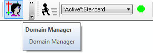
· Select Operation from InfoSWMMH2OMap SWMMBrowser.
· Expand Hydraulics by clicking on the ![]() sign, click on the Real Time Control (RTC) Rule and create one. This initiates the RTC rule editor shown below.
sign, click on the Real Time Control (RTC) Rule and create one. This initiates the RTC rule editor shown below.
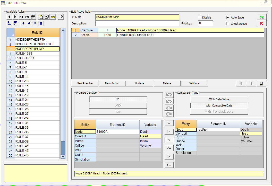
The RTC rule editor has the following regions, fields, and icons that allow editing and viewing of RTC rule data:
| Name | Description |
| Priority | Used to specify a priority index (value) for a given control rule. The priority value is used to determine which rule applies when two or more rules require that conflicting actions be taken on a link. A rule without a priority value always has a lower priority than one with a value. For two rules with the same priority value, the rule that appears first is given the higher priority. A rule with higher priority value (e.g. 2) has a precedence over the one with lower priority value (e.g. 1). |
| Disable | Used to disable or deactivate a given control rule. If unchecked the rule is considered active or operational. |
| Rule Statements | This region contains summary of the control rules specified using the subregions and editors given in theRule Clause Data. It contains the following fields or buttons:
· Type- indicates if the statement summarized on the line is a premise (condition) statement or an action statement.IF, AND, orORcould precede premise statements. Action statements could begin withTHEN,ELSE, orAND. · Key Word - specifies the conditional or logical identifier that precedes the statement given on the line. Key words could be one of IF, THEN, ELSE, AND, or OR. · Rule Statement - summarizes the condition to be satisfied before the action takes effect, or the action to be taken when condition(s) are satisfied. · Update - saves the control rule(s) available in the region to a database and closes the RTC Rule editor. · Insert - inserts the rule settings specified in the Rule Clause Data region into the Rule Statements region. · Delete -deletes the highlighted rule. · Clear - clears all the rules, not just the highlighted rule, available in the Control Rules region. · Validate -Checks and validates if the specified rule statements are acceptable (valid), and issues an error message if the statements are logically invalid. · Move Up ( |
| Rule Clause Data | This region contains subregions that enable selecting and editing of desired control rule data.
· Data Type- In this subregion the user would select the type (premise or action) of the control statement, and the corresponding Key Word for every rule statement created.Premisestatements are conditional statements that needs to be satisfied before control action is taken on the link.Premisestatements could take one ofIF,AND, orORkey words.Actionstatements are used to specify control actions to be taken on a pump, an orifice, a weir, or an outlet when the condition(s) given in one or more premise lines, preceding the action line, are satisfied. The key words that could go with action statements areTHEN,ELSE, orAND. · Object-This subregion is used to specify the InfoSWMM H2OMap SWMM data object whose hydraulic attribute is used as a controlling variable in thePremisestatement(s),or is used to indicate the link for which the control rule is being developed as indicated in theActionstatement(s). The table given below summarizes the objects that could go along with the premise statement and the action statements. ID of the object could be typed in the · Attribute- This region allows selection of the hydraulic attribute to be used as a controlling variable (forpremisestatements), or specifies the applicable action word (i.e.,StatusorSetting) foractionstatements. Acceptable attributes for each object are summarized in the table below. · Relation- used to specify the equality/inequality that applies to the rule. See the table below for applicable relations. For more information on PID Controls click here. · Value- This region is used to edit or select an attribute value or ID to be used as a point of transition to put the control action into effect. |
| STATEMENT TYPE | ACCEPTABLE OBJECTS | ACCEPTABLE ATTRIBUTES | APPLICABLE RELATION | APPLICABLE VALUE |
| PREMISE | NODE | DEPTH | =,<>,<,<=, >,>= | Numerical |
| HEAD | =,<>,<,<=, >,>= | Numerical | ||
| INFLOW | =,<>,<,<=, >,>= | Numerical | ||
| LINK | FLOW | =,<>,<,<=, >,>= | Numerical | |
| DEPTH | =,<>,<,<=, >,>= | Numerical | ||
| PUMP | STATUS | = | Open, Closed | |
| FLOW | =,<>,<,<=, >,>= | Numerical | ||
| ORIFICE | SETTING | = | Numerical | |
| WEIR | SETTING | = | Numerical | |
| SIMULATION | ELAPSED_TIME | =,<>,<,<=, >,>= | Elapsed time (decimal hours or hr:min:sec) | |
| DATE/TIME | =,<>,<,<=, >,>= | month/day/year and time of day in decimal hours or hr:min:sec | ||
| CLOCK_TIME | =,<>,<,<=, >,>= | hr:min:sec | ||
| MONTH | =,<>,<,<=, >,>= | Integer (1-12) | ||
| DAY | =,<>,<,<=, >,>= | Integer (1=Sun...7=Sat) | ||
| ACTION | PUMP | STATUS | = | Numerical |
| SETTING | = | Curve ID | ||
| SETTING | = | Time Series ID | ||
| SETTING | = | Values for P,I and D | ||
| ORIFICE | SETTING | = | Numerical | |
| SETTING | = | Curve ID | ||
| SETTING | = | Time Series ID | ||
| SETTING | = | Values for P,I and D | ||
| OUTLET | SETTING | = | Numerical | |
| SETTING | = | Curve ID | ||
| SETTING | = | Time Series ID | ||
| SETTING | = | Values for P,I and D | ||
| WEIR | SETTING | = | Numerical | |
| SETTING | = | Curve ID | ||
| SETTING | = | Time Series ID | ||
| SETTING | = | Values for P,I and D |