Setting Controls For The Pump and Orifice
Using H2OMap SWMM , you may control the operational status of pumps and flow regulating structures by specifying their initial status, using the simple control rule, or using the RTC rule functionality. You will utilize all these three features to set the operational condition of pump P20 and orifice ORIFICE1 in this section of the tutorial. For the pump, you will set the initial status (whether the pump is ON or OFF at the simulation start time) to “ON” or “Open”, and specify that the pump turns on when the water level in the storage unit feeding the pump rises above 16 feet (above the storage unit’s bottom elevation) and turns off when the water level in the feeding storage unit falls below 2 feet at any time during the simulation. For orifice ORIFICE1, you will specify that the orifice is fully open at the simulation start time, that it will be completely closed if water level in the feeding storage unit falls below 3 feet, and that the orifice will be 75% open under all other conditions.
Setting Initial Status
1. Click on the SELECT ELEMENT icon ![]() from the H2OMap SWMM EDIT NETWORK toolbar, place the cursor on pump P20 and then press the left mouse button.
from the H2OMap SWMM EDIT NETWORK toolbar, place the cursor on pump P20 and then press the left mouse button.
2. To define the initial status of pump P20, click on the TOOLS icon ![]() on the ATTRIBUTE BROWSER window, then choose the INITIAL STATUS command. The INITIAL STATUS dialog box appears on the screen.
on the ATTRIBUTE BROWSER window, then choose the INITIAL STATUS command. The INITIAL STATUS dialog box appears on the screen.
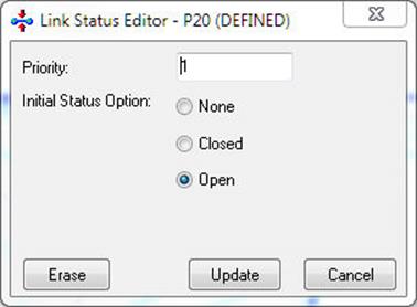
3. Set the PRIORITY to “1” and select OPEN for the INITIAL STATUS OPTION. Click on the “Update” ![]() button to save the setting and to close the dialog box.
button to save the setting and to close the dialog box.
4. Repeat steps 1 and 2 for orifice ORIFICE1. The following INITIAL STATUS dialog box appears on the screen.
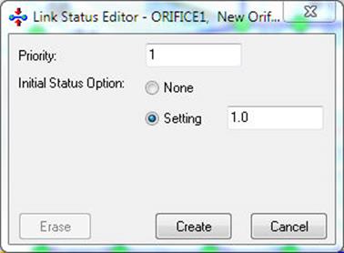
5. Set the PRIORITY value to “1” and check the SETTING field. Type “1.0” for SETTING box. Click on the “Create” ![]() button to save the setting and to close the dialog box.
button to save the setting and to close the dialog box.
Using Simple Control Rule
You will specify the operational condition of pump P20 using simple control rule. Consistent with its name, simple control can handle only simple operational control strategies, those that can be specified in terms of single operational condition.
1. Click on the SELECT ELEMENT icon ![]() from the H2OMap SWMM EDIT NETWORK toolbar, place the cursor on pump P20 and then press the left mouse button.
from the H2OMap SWMM EDIT NETWORK toolbar, place the cursor on pump P20 and then press the left mouse button.
2. To define the control rules to turn pump P20 on and off, click on the TOOLS icon ![]() on the ATTRIBUTE BROWSER
on the ATTRIBUTE BROWSER ![]() window, then choose the SIMPLE CONTROL or icon
window, then choose the SIMPLE CONTROL or icon ![]() command. The SIMPLE CONTROL DATA dialog box appears on the screen.
command. The SIMPLE CONTROL DATA dialog box appears on the screen.
3. Set the RULE PRIORITY to “1”, and make sure that the DISABLE CURRENT RULE DURING SIMULATION field is unchecked.
4. To set the condition that turns OFF the pump, specify the following control settings:
· Choose CLOSED for STATUS field.
· Choose NODE DEPTH for TYPE field.
· Type “SU5” for CONTROL NODE field. You could also graphically select the storage node by clicking on the ![]() button.
button.
· Select “<” for the OPERATOR field.
· Type “2.00” for the NODE DEPTH field, and click on the “Insert” ![]() button.
button.

5. To set the condition that turns ON the pump, specify the following control settings:
· Choose OPEN for STATUS field.
· Choose NODE DEPTH for TYPE field.
· Type “SU5” for CONTROL NODE field. You could also graphically select the storage node by clicking on the ![]() button or the icon
button or the icon ![]() command.
command.
· Select “>=” for the OPERATOR field.
· Type “16.00” for the NODE DEPTH field, and click on the“Insert” ![]() button.
button.
6. At this stage, the SIMPLE CONTROL DATA dialog box should look as shown below. Click on the “Update” ![]() button and close the dialog box.
button and close the dialog box.

Using The RTC Rule Editor in the Operation Tab of the Attribute Browser (AB)
You will specify the operational condition of orifice ORIFICE1 using the ![]() Real Time Control (RTC) rule. Unlike simple control rule, the RTC rule allows the creation of multiple conditions to be satisfied before a control action is performed. RTC rules make the definition of complex operational logic for pumps and flow regulators fully transparent and time efficient.
Real Time Control (RTC) rule. Unlike simple control rule, the RTC rule allows the creation of multiple conditions to be satisfied before a control action is performed. RTC rules make the definition of complex operational logic for pumps and flow regulators fully transparent and time efficient.
1. Select the OPERATION tab ![]() from the H2OMap SWMM BROWSER and expand the HYDRAULICS tab by clicking on the
from the H2OMap SWMM BROWSER and expand the HYDRAULICS tab by clicking on the ![]() button placed in front of it. Click once on REAL TIME CONTROL (RTC) RULES and then right-click and select the “New” command.
button placed in front of it. Click once on REAL TIME CONTROL (RTC) RULES and then right-click and select the “New” command.
2. You are then prompted to enter a new ID and description for the RTC rule. Enter “RTC1, Real Time Control” in the ![]() REAL TIME CONTROL (RTC) RULES ID field and choose the “OK” button.
REAL TIME CONTROL (RTC) RULES ID field and choose the “OK” button.

3. The dialog box now appears on the screen. Set the PRIORITY to “1”, and make sure that the DISABLE CURRENT RULE DURING SIMULATION field is unchecked.

4. To specify the condition clause, do the following:
· Choose PREMISE for DATA TYPE field, and then select IF among the available conditional key words.
· Choose NODE for the OBJECT field.
· Type “SU48” for the element specification field. You could also graphically select the storage node by clicking on the ![]() button.
button.
· Select DEPTH for the ATTRIBUTE field.
· Select “<” for the RELATION field.
· Type “3.00” for the DEPTH field.
· Click on the “Update” ![]() button.
button.

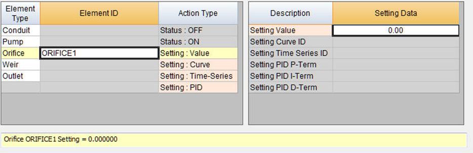
5. To specify the action clause that sets the orifice to fully closed status, do the following:
· Choose ACTION for DATA TYPE field, and then select THEN among the available conditional key words.
· Choose ORIFICE for the OBJECT field.
· Type “ORIFICE1” for the element specification field. You could also graphically select the storage node by clicking on the 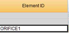
box.
· Select SETTING for the ATTRIBUTE field.
· Select “=” for the RELATION field.
· Type “0.0” for the VALUE SETTING field, and click on the “Insert” button.
6. To specify the action clause that sets the orifice to 75% open status, do the following:
· Choose ACTION for DATA TYPE field, and then select ELSE among the available conditional key words.
· Choose ORIFICE for the OBJECT field.
· Type “ORIFICE1” for the element specification field. You could also graphically select the storage node by clicking on the blank Element ID 
box.
· Select SETTING for the ATTRIBUTE field.
· Select “=” for the RELATION field.
· Type “0.75”for the VALUE SETTING field, and click on the “Insert” button.
7. At this stage, the REAL TIME CONTROL (RTC) RULES dialog box should look as shown below. Click on the “Update” button. Click on the “Save” button ![]() and close the dialog box.
and close the dialog box.
8. Turn on report control rules in the output report manager text file


 Refer to the Working with Data Objects à Real-Time Control Rules topic in the on-line H2OMap SWMM Help for further information on controls and initial status.