Porous Pavement LID Control
This is an introduction along with images of the LID Control and data require3ments in InfoSWMM. Every InfoSWMM Control uses from one to 5 layers of data - each with different data requirements. You can use the Siting Manger of InfoSWMM Sustain to find LID locations and the LID Optimizer to find the optimized number of units, cost of units, area and thickness of the LID layers based on your runoff and water quality control objectives.
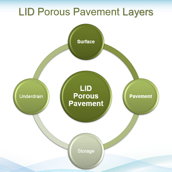
The Porous Pavement LID Control has five components or Process Layers: Surface, Pavement, Storage and Underdrain.
The Surface Process Layer consists of:
· The Storage Depth in inches or millimeters
· The Vegetative Cover Fraction (0 to 1),
· Surface Roughness (Manning’s n)
· Surface Slope (percent).


The Soil Process Layer consists of:
· Soil Thickness in inches or millimeters,
· Porosity as a Fraction (0 to 1),
· Field Capacity as a Fraction (0 to 1),
· Wilting Point as a Fraction (0 to 1),
· Conductivity (inches/hour or millimeters/hour),
· Conductivity Slope,
· Suction Head (inches/hour or millimeters/hour)


The Pavement Process Layer consists of:
· The Pavement Thickness in inches or millimeters
· The Void Ratio (Voids/Solids) (0 to 1),
· Impervious Surface Fraction,
· Pavement Permeability in inches/hour or millimeters per hour,
· Clogging Factor (fraction).

The Storage Process Layer consists of:
· The Storage Height in inches or millimeters,
· The Void Ratio as a Fraction (0 to 1),
· Surface Conductivity in inches/hour or millimeters/hour,
· Clogging Factor


The Underdrain Process Layer consists of:
· Drain Coefficient (inches/hour or millimeters/hour)
· The Void Ratio as a Fraction (0 to 1),
· Drain Exponent
· Drain Offset Height (inches or millimeters)


An example of a Porous Pavement Driveway.
The four layers used in a simulation for a Permeable Pavement LID are shown in the following image.
Low Impact Development Pavement Layer
The Pavement Layer page of the LID Control Editor supplies values for the following properties of a porous pavement LID:
Thickness
The thickness of the pavement layer (inches or mm). Typical values are 4 to 6 inches (100 to 150 mm).
Void Ratio
The volume of void space relative to the volume of solids in the pavement for continuous systems or for the fill material used in modular systems. Typical values for pavements are 0.12 to 0.21. Note that porosity = void ratio / (1 + void ratio).
Impervious Surface Fraction
Ratio of impervious paver material to total area for modular systems; 0 for continuous porous pavement systems.
Permeability
Permeability of the concrete or asphalt used in continuous systems or hydraulic conductivity of the fill material (gravel or sand) used in modular systems (in/hr or mm/hr). The permeability of new porous concrete or asphalt is very high (e.g., hundreds of in/hr) but can drop off over time due to clogging by fine particulates in the runoff (see below).
Clogging Factor
Number of pavement layer void volumes of runoff treated it takes to completely clog the pavement. Use a value of 0 to ignore clogging. Clogging progressively reduces the pavement's permeability in direct proportion to the cumulative volume of runoff treated.
If one has an estimate of the number of years it takes to fully clog the system (Yclog), the Clogging Factor can be computed as: Yclog * Pa * CR * (1 + VR) * (1 - ISF) / (T * VR) where Pa is the annual rainfall amount over the site, CR is the pavement's capture ratio (area that contributes runoff to the pavement divided by area of the pavement itself), VR is the system's Void Ratio, ISF is the Impervious Surface Fraction, and T is the pavement layer Thickness.
As an example, suppose it takes 5 years to clog a continuous porous pavement system that serves an area where the annual rainfall is 36 inches/year. If the pavement is 6 inches thick, has a void ratio of 0.2 and captures runoff only from its own surface, then the Clogging Factor is 5 x 36 x (1 + 0.2) / 6 / 0.2 = 180.
Excerpt from the EPA manual Storm Water Management Model Reference Manual Volume III – Water Quality (PDF) which can be found here


6.5.1 Permeable Pavement Parameter Values
Table 6-6 lists typical parameter ranges for permeable pavement installations. The maximum storage height on the surface layer, D1, now represents the depth of depression storage on the pavement surface. Its suggested range is characteristic of impervious surfaces in general (ASCE, 1992). The pavement layer properties in the table distinguish between continuous concrete or asphalt pavement systems and block paver systems.
UNHSC (2009) recommends that the optional sand filter layer be composed of coarse sand/fine gravel (bank run gravel). It aids in pollutant removal and in slowing down the movement of water through the unit. Because of the very high conductivity of permeable pavement, with no sand layer present the unit acts in the same manner as an infiltration trench whose change in water level over each time step is simply the difference between the applied surface inflow rate and the exfiltration rate out of the bottom (assuming no underdrain).
Table 6-6 Typical ranges for permeable pavement parameters
| Parameter | Range |
| Surface Depression Storage, inches (D1) | 0 – 0.1 |
| Surface Void Fraction (f1) | 1.0 |
| Pavement Thickness, inches (D4) | 3 – 8 |
| Continuous Pavement: | |
| Porosity (f4) | 0.15 – 0.25 |
| Permeability, in/hr (K4) | 28 – 1750 |
| Surface Opening Fraction (1 – F4) | 0 |
| Block Pavers: | |
| Porosity (f4) | 0.1 – 0.4 |
| Permeability, in/hr (K4) | 5 – 150 |
| Surface Opening Fraction (1 – F4) | 0.08 – 0.10 |
| Sand Filter Layer: | |
| Thickness, inches (D2) | 8 – 12 |
| Porosity (f2) | 0.25 – 0.35 |
| Field Capacity (qFC) | 0.15 – 0.25 |
| Wilting Point (qWP) | 0.05 – 0.10 |
| Saturated Hydraulic Conductivity, in/hr (K2S) | 5 – 30 |
| Wetting Front Suction Head, inches (y2) | 2 – 4 |
| Percolation Parameter (HCO) | 30 – 55 |
| Storage Layer Thickness, inches (D3) | 6 – 36 |
| Storage Void Fraction (f3) | 0.2 – 0.4 |
| Capture Ratio (RLID) | 0 – 5 |