Rooftop Disconnection LID Control in InfoSWMM and #SWMM5 for Sustain
This is an introduction along with images of the LID Control and data require3ments in InfoSWMM. Every InfoSWMM Control uses from one to 5 layers of data - each with different data requirements. You can use the Siting Manger of InfoSWMM Sustain to find LID locations and the LID Optimizer to find the optimized number of units, cost of units, area and thickness of the LID layers based on your runoff and water quality control objectives.
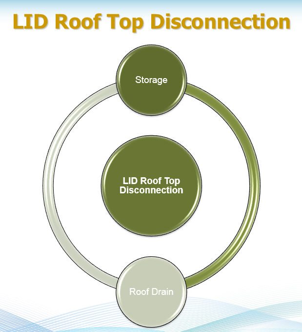
Rooftop Disconnection has two process layers: (1) Surface and (2) Roof Drain
LID controls are represented by a combination of vertical layers whose properties are defined on a per-unit-area basis. This allows LIDs of the same design but differing areal coverage to easily be placed within different Subcatchments in a study area.
During a simulation SWMM performs a moisture balance that keeps track of how much water moves between and is stored within each LID layer. As an example, the layers used to model a bio-retention cell and the flow pathways between them are shown below:
The following table indicates which combination of layers applies to each type of LID (x means required, o means optional):
| LID Type | Surface | Pavement | Soil | Storage | Drain | Drainage Mat |
| Bio-Retention Cell | x | x | x | o | ||
| Rain Garden | x | x | ||||
| Green Roof | x | x | x | |||
| Infiltration Trench | x | x | o | |||
| Permeable Pavement | x | x | o | x | o | |
| Rain Barrel | x | x | ||||
| Rooftop Disconnection | x | x | ||||
| Vegetative Swale | x |
When a user adds a specific type of LID control object to a InfoSWMM project the LID Control Editor is used to set the design properties of each relevant layer (such as thickness, void volume, hydraulic conductivity, drain characteristics, etc.). These LID objects can then be placed within selected Subcatchments at any desired sizing (or areal coverage) by editing the Subcatchment's LID Controls property.
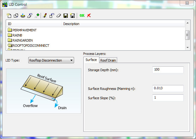

The Roof Drain Process Layer of the RoofTop Disconnection consists of:
· Flow Capacity (inches/hour or millimeters/hour)


The two layers used in a simulation for a Rooftop Disconnection LID are shown in the following image.
Excerpt from the EPA manual Storm Water Management Model Reference Manual Volume III – Water Quality (PDF) which can be found here


6.5.1 Rooftop Disconnection
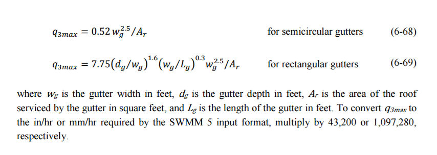
The parameters required for rooftop disconnection are the length of the flow path for roof runoff (the inverse of the W1/A1 term in Equation 6-21), the roof slope, the roughness coefficient for the roof surface, the depression storage depth of the roof’s surface, and the flow capacity of the roof drain system (q3max).
The flow path length and its slope are obtained directly from the roof’s dimensions. Roughness coefficients for roofing material would be similar to those for asphalt and clay tile, 0.013 to
0.016. Depression storage would range from 0.05 to 0.1 inches with sloped roofs at the low end of this range and flat roofs having possibly higher values. The flow capacity of the roof’s gutters in ft/sec can be estimated from the following equations (Beij, 1934):