Pump Attributes for better Pump Simulations in InfoSWMM and InfoSWMM SA
Like all other visual data objects, pump object is edited using the attribute browser.
To edit attributes of a pump;
- Switch the map to Object Selection mode by clicking
 from InfoSWMM H2OMap SWMM InfoSWMM SA Edit Network tool bar.
 - Select the pump whose attributes are to be edited by clicking the mouse on the pump. This process will initiate the attribute browser given below. Description of each of these attributes is also presented below.
- In addition to the parameters listed in the attribute browser, pumps may also require definition of Initial Status
 and Control
  . Attribute editor of these pump operation rules could also be initiated by first selecting a pump, clicking on the
  icon located at the second row of the top of the attribute browser, and then clicking on the desired feature from the initiated pop up menu.
 - Pump energy use can also be monitored. Use the Pump Energy button
 and the Pump Efficiency button
  to access the data. See Pump Energy Management for more information.
 - Pump / Force Main System
- Wet Well and its associated physical parameters,
- Pump Type
- Defined Pump Curve,
- Downstream Pressure Node and
- Downstream Force Main

 |
(ID) - User-assigned pump name.
Description - Optional description of the pump. Start Node - Name of node on the inlet end of the pump - this is normally the wet well but pumps can also operate with a manhole End Node - Name of node on the outlet end of the pump - this is the starting node of the force main. Pump Curve ID - Name of the Pump Curve which contains the pump's operating data (double-click to edit the curve). There are four types of pump (see Pumps - Desciption). Pump type is specified by choosing the correct curve type from the Curve editor. Ideal Pump - Select Yes/No to specify an "Ideal Pump". An Ideal Pump is used to pump at a rate equal to the inflow at the inlet node and does not use a pump curve. Since an ideal pump pumps all of the flow from the upstream node, the upstream node must not have any other links exiting from it. Startup Depth - Depth of Storage at the inlet node when pump turns on Shutoff Depth - Depth of storage at the inlet node when pump turns off. This field can be populated automatically using the Level Control tool. See below. This can also be accomplished by defining a control. See below. Initial Status - Helps to specify the On or Off status of the pump at the simulation start time. Click the Control - Helps to supply simple pump operational control rule. Click the Level Control - This tool User Tag - Optional label used to identify or categorize the pump. Year of Installation - Optional. The year the pump is installed. Year of Retirement - Optional. The year the pump will be retiring. Zone - Optional zone to which the pump belongs. Phase - Optional phase of the project. |
Your basic force main/pump system consists of:
- Wet Well and its associated physical parameters,
- Pump Type
- Defined Pump Curve,
- Downstream Pressure Node and
- Downstream Force Main
Figure 1: The Basic System

Step 1: Wet Well Data
Enter the invert elevation, maximum depth of the Wet Well, the physical shape as either a function or shape table and any evaporation or infiltration.
Step 2: Define the Pump Type
The Pump type is defined by a Pump Curve and the On and Off elevations:
The four types of pumps are:
- Volume - Flow
- Depth – Flow
- Head – Flow
- Depth - Flow

Step 3: Define the Pump Curve in the Operation Tab

Step 4: Set a Surcharge or Pressure Depth at the Downstream end of the Pump
Any positive Surcharge Depth in the Node will allow the program during the simulation to keep the node under pressure forcing flow through the Force Main.
Step 5: Force Main Data
Define the downstream pipe(s) from the pump as Force Main conduits with either a Hazen Williams or Darcy-Weisbach coefficient (defined in the Run Manager of InfoSWMM)


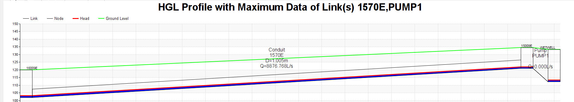
Step 6: HGL Plot of the Force Main System
Step 7: Pump Summary in the RPT File
