Control Rules in SWMM5 and InfoSWMM
Operational control rules determine how pumps and flow regulating structures (i.e., orifice and weir) in the conveyance system will be adjusted over the course of a simulation. InfoSWMM and InfoSWMM SA has the following three control classes.
· Initial Status - The initial status editor enables specification of status of pumps, orifices, and weirs at simulation start time.
· Simple Controls - As the name implies, simple controls can handle only simple operational control strategies, those that can be specified in terms of single operational condition.
· Real-Time Control (RTC) Rule -InfoSWMM and InfoSWMM SA offers an advanced RTC rule that could be used to effectively simulate the operation of pumps and flow regulating structures such as weirs and orifices. Unlike Simple Controls, RTC rules allow creation of multiple conditions to be satisfied before a control action is performed. RTC rules make the definition of complex operational logic for pumps and interdependent regulators fully transparent and time efficient. Each regulator or pump operates under the control logic encapsulated into a set of simple logical rules and control functions. The system allows a schematized definition of any form and size of decision tree due to the flexibility of InfoSWMM and InfoSWMM SA Rule Format, featuring conditional clauses, action clauses and logical and conditional operators including IF, THEN, ELSE, AND, and OR in any combination. InfoSWMM and InfoSWMM SA RTC Rule Editor immensely simplifies the process of creating this potentially complex and challenging operational rule.
Simple time-based pump control:
RULE R1
IF SIMULATION TIME > 8
THEN PUMP 12 STATUS = ON
ELSE PUMP 12 STATUS = OFF
Multiple-condition orifice gate control:
RULE R2A
IF NODE 23 DEPTH > 12
AND LINK 165 FLOW > 100
THEN ORIFICE R55 SETTING = 0.5
RULE R2B
IF NODE 23 DEPTH > 12
AND LINK 165 FLOW > 200
THEN ORIFICE R55 SETTING = 1.0
RULE R2C
IF NODE 23 DEPTH <= 12
OR LINK 165 FLOW <= 100
THEN ORIFICE R55 SETTING = 0
Pump station operation:
RULE R3A
IF NODE N1 DEPTH > 5
THEN PUMP N1A STATUS = ON
RULE R3B
IF NODE N1 DEPTH > 7
THEN PUMP N1B STATUS = ON
RULE R3C
IF NODE N1 DEPTH <= 3
THEN PUMP N1A STATUS = OFF
AND PUMP N1B STATUS = OFF
New to Innovyze SWMM 14.5 Update 5
C.3 Control Rules Editor
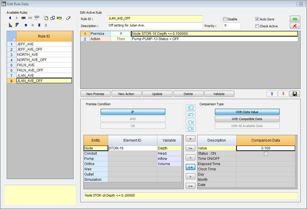
The Control Rules Editor is invoked whenever a new control rule is created or an existing rule is selected for editing. The editor contains a memo field where the entire collection of control rules is displayed and can be edited.
Control Rule Format
Each control rule is a series of statements of the form:
RULE ruleID
IF condition_1
AND condition_2
OR condition_3
AND condition_4
Etc.
THEN action_1
AND action_2
Etc.
ELSE action_3
AND action_4 Etc.
PRIORITY value
where keywords are shown in boldface and ruleID is an ID label assigned to the rule, condition_n is a Condition Clause, action_n is an Action Clause, and value is a priority value (e.g., a number from 1 to 5). The formats used for Condition and Action clauses are discussed below.
Only the RULE, IF and THEN portions of a rule are required; the ELSE and PRIORITY portions are optional.
Blank lines between clauses are permitted and any text to the right of a semicolon is considered a comment.
When mixing AND and OR clauses, the OR operator has higher precedence than AND, i.e.,
IF A or B and C is equivalent to
IF (A or B) and C.
If the interpretation was meant to be
IF A or (B and C)
then this can be expressed using two rules as in
IF A THEN ...
IF B and C THEN ...
The PRIORITY value is used to determine which rule applies when two or more rules require that conflicting actions be taken on a link. A conflicting rule with a higher priority value has precedence over one with a lower value (e.g., PRIORITY 5 outranks PRIORITY 1). A rule without a priority value always has a lower priority than one with a value. For two rules with the same priority value, the rule that appears first is given the higher priority.
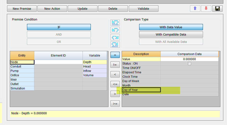
Condition Clauses
A Condition Clause of a control rule has the following formats:
object id attribute relation value object id attribute relation object id attribute
where:
| object | = | a category of object |
| id | = | the object's ID label |
| attribute | = | an attribute or property of the object |
| relation | = | a relational operator (=, <>, <, <=, >, >=) |
| value | = | an attribute value |
Some examples of condition clauses are:
NODE N23 DEPTH > 10
NODE N23 DEPTH > NODE N25 DEPTH PUMP P45 STATUS = OFF
SIMULATION CLOCKTIME = 22:45:00
The objects and attributes that can appear in a condition clause are as follows:
| Object | Attributes | Value |
| NODE | DEPTH HEAD
VOLUME INFLOW |
numerical value numerical value numerical value numerical value |
| LINK | FLOW
DEPTH TIMEOPEN TIMECLOSED |
numerical value numerical value decimal hours or hr:min decimal hours or hr:min |
| CONDUIT | STATUS
TIMEOPEN TIMECLOSED |
OPEN or CLOSED
decimal hours or hr:min decimal hours or hr:min |
| PUMP | STATUS
SETTING FLOW TIMEOPEN TIMECLOSED |
ON or OFF pump curve multiplier numerical value decimal hours or hr:min decimal hours or hr:min |
| ORIFICE | SETTING
TIMEOPEN TIMECLOSED |
fraction open decimal hours or hr:min decimal hours or hr:min |
| WEIR | SETTING TIMEOPEN
TIMECLOSED |
fraction open decimal hours or hr:min decimal hours or hr:min |
| OUTLET | SETTING
TIMEOPEN TIMECLOSED |
rating curve multiplier decimal hours or hr:min decimal hours or hr:min |
| SIMULATION | TIME | elapsed time in decimal hours or hr:min:sec |
| SIMULATION | DATE
MONTH DAY CLOCKTIME |
month/day/year month of year (January = 1) day of week (Sunday = 1) time of day in hr:min:sec |
TIMEOPEN is the duration a link has been in an OPEN or ON state or have its SETTING be greater than zero; TIMECLOSED is the duration it has remained in a CLOSED or OFF state or have its SETTING be zero.
Action Clauses
An Action Clause of a control rule can have one of the following formats:
PUMP id STATUS = ON/OFF
PUMP/ORIFICE/WEIR/OUTLET id SETTING = value
where the meaning of SETTING depends on the object being controlled:
§ for Pumps it is a multiplier applied to the flow computed from the pump curve,
§ for Orifices it is the fractional amount that the orifice is fully open,
§ for Weirs it is the fractional amount of the original freeboard that exists (i.e., weir control is accomplished by moving the crest height up or down),
§ for Outlets it is a multiplier applied to the flow computed from the outlet's rating curve.
Some examples of action clauses are: PUMP P67 STATUS = OFF
ORIFICE O212 SETTING = 0.5
Modulated Controls
Modulated controls are control rules that provide for a continuous degree of control applied to a pump or flow regulator as determined by the value of some controller variable, such as water depth at a node, or by time. The functional relation between the control setting and the controller variable can be specified by using a Control Curve, a Time Series, or a PID Controller. Some examples of modulated control rules are:
RULE MC1
IF NODE N2 DEPTH >= 0
THEN WEIR W25 SETTING = CURVE C25
RULE MC2
IF SIMULATION TIME > 0
THEN PUMP P12 SETTING = TIMESERIES TS101
RULE MC3
IF LINK L33 FLOW <> 1.6
THEN ORIFICE O12 SETTING = PID 0.1 0.0 0.0
Note how a modified form of the action clause is used to specify the name of the control curve, time series or PID parameter set that defines the degree of control. A PID parameter set contains three values -- a proportional gain coefficient, an integral time (in minutes), and a derivative time (in minutes). Also, by convention the controller variable used in a Control Curve or PID Controller will always be the object and attribute named in the last condition clause of the rule. As an example, in rule MC1 above Curve C25 would define how the fractional setting at Weir W25 varied with the water depth at Node N2. In rule MC3, the PID controller adjusts the opening of Orifice O12 to maintain a flow of 1.6 in Link L33.
PID Controllers
A PID (Proportional-Integral-Derivative) Controller is a generic closed-loop control scheme that tries to maintain a desired set-point on some process variable by computing and applying a corrective action that adjusts the process accordingly. In the context of a hydraulic conveyance system a PID controller might be used to adjust the opening on a gated orifice to maintain a target flow rate in a specific conduit or to adjust a variable speed pump to maintain a desired depth in a storage unit. The classical PID controller has the form:
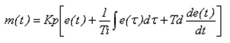
where:
| m(t) | = | controller output |
| Kp | = | proportional coefficient (gain) |
| Ti | = | integral time (minutes) |
| Td | = | derivative time (minutes) |
| e(t) | = | error (difference between setpoint and observed variable value) |
| t | = | time. |
The performance of a PID controller is determined by the values assigned to the coefficients Kp, Ti, and Td.
The controller output m(t) has the same meaning as a link setting used in a rule's Action Clause while dt is the current flow routing time step in minutes. Because link settings are relative values (with respect to either a pump's standard operating curve or to the full opening height of an orifice or weir) the error e(t) used by the controller is also a relative value. It is defined as the difference between the control variable setpoint x* and its value at time t, x(t), normalized to the setpoint value: e(t) = (x* - x(t)) / x*.
Note that for direct action control, where an increase in the link setting causes an increase in the controlled variable, the sign of Kp must be positive. For reverse action control, where the controlled variable decreases as the link setting increases, the sign of Kp must be negative. The user must recognize whether the control is direct or reverse action and use the proper sign on Kd accordingly. For example, adjusting an orifice opening to maintain a desired downstream flow is direct action. Adjusting it to maintain an upstream water level is reverse action. Controlling a pump to maintain a fixed wet well water level would be reverse action while using it to maintain a fixed downstream flow is direct action.
How does a PID controller work in InfoSWMM / InfoSWMM SA and SWMMM 5
double getPIDSetting(struct TAction* a, double dt) // at each time step find the PID control changes for the current time step dt
// Input: a = an action object
// dt = current time step (days)
// Output: returns a new link setting
// Purpose: computes a new setting for a link subject to a PID controller.
// Note: a->kp = gain coefficient,
// a->ki = integral time (minutes)
// a->k2 = derivative time (minutes)
// a->e1 = error from previous time step
// a->e2 = error from two time steps ago
{
double e0, setting;
double p, i, d, update;
double tolerance = 0.0001;
// — convert time step from days to minutes
dt *= 1440.0;
// — determine relative error in achieving controller set point
// Or how close are we to the set point?
e0 = SetPoint – ControlValue;
if ( fabs(e0) > TINY )
{
if ( SetPoint != 0.0 ) e0 = e0/SetPoint;
// now alter the value of e0
else e0 = e0/ControlValue;
}
// — reset previous errors to 0 if controller gets stuck
if (fabs(e0 – a->e1) < tolerance)
{
a->e2 = 0.0;
a->e1 = 0.0;
}
// — use the recursive form of the PID controller equation to
// determine the new setting for the controlled link
Here is a view of the p, i and d PID internal parameters https://www.wikiwand.com/en/PID_controller
A block diagram of a PID controller in a feedback loop
p = (e0 – a->e1);
ki, id, kp are user inputs in InfoSWMM and SWMM5 or from the EPA SWMM 5 Help File
if ( a->ki == 0.0 ) i = 0.0;
else i = e0 * dt / a->ki;
d = a->kd * (e0 – 2.0*a->e1 + a->e2) / dt;
update = a->kp * (p + i + d);
if ( fabs(update) < tolerance ) update = 0.0;
setting = Link[a->link].targetSetting + update;
// — update previous errors
a->e2 = a->e1;
a->e1 = e0;
// — check that new setting lies within feasible limits
// If the link is not a pump then the setting must be between 0 and 1
if ( setting < 0.0 ) setting = 0.0;
if (Link[a->link].type != PUMP && setting > 1.0 ) setting = 1.0;
return setting;}
Privileged and Confidential Communication: This electronic mail communication and any documents included hereto may contain confidential and privileged material for the sole use of the intended recipient(s) named above. If you are not the intended recipient (or authorized to receive for the recipient) of this message, any review, use, distribution or disclosure by you or others is strictly prohibited. Please contact the sender by reply email and delete and/or destroy the accompanying message.