Available Report Types in InfoSewer
Reports may be viewed in the Output Report manager as shown below.
Click on any portion for more information:


The following report types are available from the Output Report Manager. Choose a report for more information:
Static Loading Manhole Report
Shows steady state simulation results for all manholes in tabular format. The report displays one record for each manhole in the current project. Manhole report columns include the Node Identifier, Rim Elevation, Load, Overload and Grade, surcharge status, occurrence of a hydraulic jump across the node and the unfilled and surcharged depth.
The following variables are displayed on the Static Loading Manhole Report in the Output Report Manager for all or selected manholes:

- ID - Manhole node identifier.
- Rim Elevation - Manhole node elevation, ft (m).
- Base Flow - The base loading applied to the manhole (before peaking), flow units.
- Total Flow - The calculated flow (after peaking), inserted into the manhole, flow units.
- Storm Flow - Peak storm load at the manhole, flow units
- Grade - Manhole node hydraulic grade for the steady state simulation, ft (m).
- Status - Surcharge status of the manhole.
- Hydraulic Jump – Was there a Hydraulic Jump between the incoming and outgoing pipe of the node?
- Unfilled Depth – Depth between the node Rim Elevation and the Node Grade. A zero value indicates it is full.
- Surcharge Depth - Is the difference of “The Depth of Water of Manhole” and “The Crown of the Highest Connecting Conduits”. A positive Surcharge Depth means the node water surface elevation is above the highest pipe crown, a negative depth means that the node depth is below the highest pipe crown.
![]()
Static Chamber Manhole Report
Shows steady state simulation results for all chamber manholes in tabular format. The report displays one record for each chamber manhole in the current project. Chamber manhole report columns include the Node Identifier and the Hydraulic Grade.
The following variables are displayed on the Static Chamber Manhole Report in the Output Report Manager for all or selected chamber manholes:
- ID - Chamber manhole node identifier.
- Grade - Chamber manhole node hydraulic grade for the steady state simulation, ft (m).
![]()
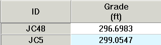
Static Outlet Report
Shows steady state simulation results for all outlets in tabular format. The report displays one record for each outlet in the current project. Outlet report columns include the Node Identifier, Flow and Hydraulic Grade.
The following variables are displayed on the Static Outlet Report in the Output Report Manager for all or selected outlets:
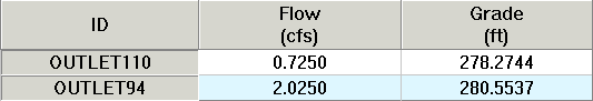
- ID - Outlet node identifier.
- Flow - The peaked flow exiting the system at the outlet structure, flow units.
- Grade - The hydraulic grade at the outlet structure for the steady state simulation, ft (m).
![]()
Static Wet Well Report
Shows steady state simulation results for all wet wells in tabular format. The report displays one record for each wet well in the current project. Wet well report columns include the Node Identifier and Hydraulic Grade.
The following variables are displayed on the Static Wet Well Report in the Output Report Manager for all or selected wet wells:
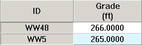
- ID - Wet well node identifier.
- Grade - The hydraulic grade at the outlet structure for the steady state simulation, ft (m).
Static Gravity Main Report
Shows steady state simulation results for all gravity mains in tabular format. The report displays one record for each gravity main in the current project. Gravity main report columns include the Node Identifier, Total Flow, Unpeakable Flow, Peakable Flow, Coverage Flow, Infiltration Flow, Storm Flow, Flow Type, Velocity, d/D, q/Q, Water Depth, Critical Depth, Full Flow, Coverage Count, Backwater Adjustment, Adjusted Depth and Adjusted Velocity.
The following variables are displayed on the Static Gravity Main Report in the Output Report Manager for all or selected gravity mains:


- ID - Gravity main identifier.
- From Node - ID of upstream node.
- To Node - ID of downstream node.
- Diameter - Inside pipe diameter for circular channels, in (mm).
- Channel Depth - Maximum depth of a conduit (for non-circular channels only), in (mm).
- Channel Width - Top/Bottom width of a conduit (for non-circular channels only), in (mm).
- Channel Left Slope - Left side slope of a conduit (for trapezoidal and triangular channels only).
- Channel Right Slope - Right side slope of a conduit (for trapezoidal and triangular channels only).
- Length - Pipe length, ft (m).
- Slope - Ratio of the change in vertical distance to the change in horizontal distance, unitless.
- Total Flow - The summation of all flow types, flow unit.
- Unpeakable Flow - The flow to which no peaking is applied, flow unit.
- Peakable Flow - The flow derived based on the Federov peaking equation, flow unit.
- Coverage Flow - The flow derived based on the Harman and Babbitt peaking equation in reference to the contributing population, flow unit.
- Infiltration Flow - The volume of groundwater entering the sewer system from the soil through defective joints, broken or cracked pipes, improper connections, or manhole walls, flow unit.
- Storm Flow - Peak storm load in the pipe, flow units.
- Flow Type - Indicates if the flow is pressurized or free surface.
- Velocity - The speed with which the water is traveling through the pipe, in ft/s (m/s).
- d/D - The ratio of actual flow depth to the diameter of the pipe (full flow depth), unitless.
- q/Q - The ratio of actual flow to the full flow as derived based on Manning's Equation, unitless.
- Water Depth - The depth of water as it is flowing through the pipe, ft (m).
- Critical Depth - The depth of water resulting when the Froude Number is equal to 1.0, ft (m).
- Full Flow - The capacity of the pipe as evaluated based on Manning's Equation (d/D = 1.0), flow units.
- Coverage Count - The population parameter used in the Harman and Babbitt equations.
- Backwater Adjustment – If the downstream head of the link is greater than the flow depth + the downstream pipe invert then the adjusted depth is one half of the sum of the water surface depth at the upstream and downstream ends of the link.
- Adjusted Depth – The adjusted depth is the average of the upstream plus the downstream adjusted depth, where the upstream adjusted depth is the upstream head minus the upstream pipe invert elevation and the downstream adjusted depth is the downstream head minus the downstream pipe invert elevation. The adjusted depth is the minimum of the pipe diameter and the computed pipe adjusted depth.
- Adjusted Velocity – the adjusted depth is used to calculate the wet area and adjusted velocity = flow/wet area.
![]()
Static Force Main Report
Shows steady state simulation results for all force mains in tabular format. The report displays one record for each force main in the current project. Force main report columns include the Node Identifier, from ID, to ID, Diameter, Length, Flow, Velocity and Headloss.
The following variables are displayed on the Static Force Main Report in the Output Report Manager for all or selected force mains:
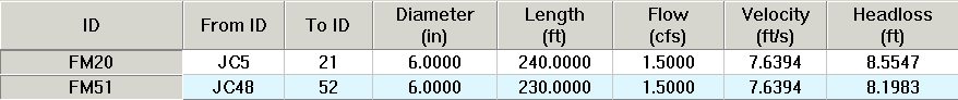
- ID - Force main identifier.
- From ID - ID of upstream node.
- To ID - ID of downstream node.
- Diameter - Inside pipe diameter, in (mm).
- Length - Pipe length, ft (m).
- Flow - The flow passing through the force main (as derived from the upstream pump), flow units. identifier.
- Velocity - The velocity of flow passing through the force main, flow units.
- Headloss - The total headloss experienced across the force main, ft (m).
![]()
Static Pump Report
Shows steady state simulation results for all pumps in tabular format. The report displays one record for each pump in the current project. Pump report columns include the Node Identifier, from ID, to ID, Flow, Head Increase, Usage and Pump Speed.
The following variables are displayed on the Static Pump Report in the Output Report Manager for all or selected pumps:

- ID - Pump identifier.
- From ID - ID of upstream node.
- To ID - ID of downstream node.
- Flow - The flow rate passing through the pump, flow units.
- Head Increase - The hydraulic head increase the pump is lifting sewage flows, ft (m).
- Power - The power imparted by the pump, hp (kw)
- Usage - The number of pumps in the simulation.
- Speed – Pump Speed based on the pump affinity laws in the controls.
![]()
Pipe Design Report
Shows results for a steady state design simulation in tabular format. The report displays one record for each gravity main in the current project. Pipe design report columns include the Node Identifier, from ID, to ID, diameter, length, original velocity, d/D Ratio, Analysis Flow, Analysis Excess, Analysis d/D Ratio, Design Flow, Design Excess, Design d/D Ratio, Replacement Diameter, Replacement Velocity, Replacement d/D Ratio, Replacement Cost, Parallel Diameter, Parallel Velocity, Parallel d/D Ratio and Parallel Cost.
Click here for details.
![]()
EPS Loading Manhole Report
Shows extended period simulation results for all manholes in tabular format at a specified time step. The report displays one record for each manhole in the current project. Manhole report columns include the Node Identifier, Rim Elevation, Load, Storm Flow, Total Storm Flow, Grade, Surcharge Status, occurrence of a hydraulic jump across the node, Unfilled Depth, Surcharged Depth and Quality. The Froude Number defines the subcritical flow or Supercritical flow. A Froude number greater than 1 is a Supercritical flow whereas a Froude number less than 1 is a subcritical flow. In order to have a hydraulic jump the Froude number needs to be greater than or equal to 1 in a Sewer link. A hydraulic jump occurs when the flow goes from Supercritical flow (Fr > 1) to Subcritical flow (Fr < 1) or from an unstable flow to a stable flow. A hydraulic jump will not occur when a flow goes from subcritical flow (Fr < 1) to a Supercritical flow (Fr > 1), Sewer flags a node as having a jump if the upstream link (at the upstream end of the link) is Supercritical and the downstream link is Subcritical based on the Froude Number.
The following variables are displayed on the EPS Loading Manhole Report in the Output Report Manager for all or selected manholes:
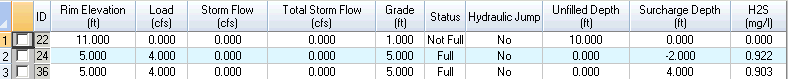
- ID - Manhole node identifier.
- Rim Elevation - Manhole node elevation, ft (m).
- Load - The base loading applied to the manhole at that particular time step, flow units.
- Storm Flow - The storm flow entering the system at the manhole, flow units
- Total Storm Flow -Storm load at the manhole including contributions from upstream subcatchments, flow units.
- Grade - Manhole node hydraulic grade for the steady state simulation, ft (m).
- Status - Surcharge status of the manhole.
- Hydraulic Jump – Was there a Hydraulic Jump between the incoming and outgoing pipes of the node?
- Unfilled Depth – depth between the node Rim Elevation and the Node Grade. A zero value indicates it is full.
- Surcharge Depth - is the difference of “The Depth of Water of Manhole” and “The Crown of the Highest Connecting Conduits”. A positive Surcharge Depth means the node water surface elevation is above the highest pipe crown, a negative depth means that the node depth is below the highest pipe crown.
- Quality - Reports the simulated water quality. The model supporting simulation of seven different water quality modules including (hydrogen sulfide, corrosion, sediment transport and deposition, BOD, pollutant (contaminant) transport, time of concentration (flow age), and trace).
![]()
EPS Chamber Manhole Report
Shows extended period simulation results for all chamber manholes in tabular format at a specific timestep. The report displays one record for each chamber manhole in the current project. Chamber manhole report columns include the Node Identifier, Hydraulic Grade and Quality.
The following variables are displayed on the EPS Chamber Manhole Report in the Output Report Manager for all or selected chamber manholes:

- ID - Chamber manhole node identifier.
- Grade - Chamber manhole node hydraulic grade for the extended period simulation timestep, ft (m).
- Quality - Reports the simulated water quality. The model supporting simulation of seven different water quality modules including (hydrogen sulfide, corrosion, sediment transport and deposition, BOD, pollutant (contaminant) transport, time of concentration (flow age), and trace).
![]()
EPS Outlet Report
Shows extended period simulation results for all outlets in tabular format at a specific timestep. The report displays one record for each outlet in the current project. Outlet report columns include the Node Identifier, Flow, Hydraulic Grade and Quality.
The following variables are displayed on the EPS Outlet Report in the Output Report Manager for all or selected outlets:

- ID - Outlet node identifier.
- Flow - The peaked flow exiting the system at the outlet structure, flow units.
- Grade - The hydraulic grade at the outlet structure for the extended period simulation timestep, ft (m).
- Quality - Reports the simulated water quality. The model supporting simulation of seven different water quality modules including (hydrogen sulfide, corrosion, sediment transport and deposition, BOD, pollutant (contaminant) transport, time of concentration (flow age), and trace).
![]()
EPS Wet Well Report
Shows extended period simulation results for all wet wells in tabular format at a specific timestep. The report displays one record for each wet well in the current project. Wet well report columns include the Node Identifier, Bottom Elevation, Water Level, Hydraulic Grade, Stored Volume, Percent Full, Overflow and Quality.
The following variables are displayed on the EPS Wet Well Report in the Output Report Manager for all or selected wet wells:
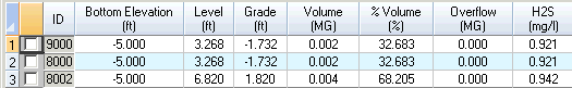
- ID - Wet well node identifier.
- Bottom Elevation - Elevation of the wet well above datum, ft (m).
- Level - Water level above the bottom elevation of the wet well, ft (m).
- Grade - The hydraulic grade at the outlet structure for the steady state simulation, ft (m).
- Volume - The total volume of sewage being stored in the wet well, volume units.
- % Volume - Percent full status of the wet well as calculated between the high and low water levels specified for the wet well, %.
- Overflow - Amount of water stored in the wet well that exceeds the storage capacity of the wet well. This field will only be populated when the wet well is full and when flows entering the wet well exceed the pumping capacity of the lift station.
- Quality - Reports the simulated water quality. The model supporting simulation of seven different water quality modules including (hydrogen sulfide, corrosion, sediment transport and deposition, BOD, pollutant (contaminant) transport, time of concentration (flow age), and trace).
EPS Gravity Main Report
Shows extended period simulation results for all gravity mains in tabular format at a specific timestep. The report displays one record for each gravity main in the current project. Gravity main report columns include the Node Identifier, from ID, to ID, Diameter, Length, Slope, Flow, Flow Type, Velocity, Water Depth, Froude Number, Overflow, Backwater Adjustment, Adjusted Depth, Adjusted Velocity, d/D ratio, q/Q ratio and Quality.
The following variables are displayed on the EPS Gravity Main Report in the Output Report Manager for all or selected gravity mains:


- ID - Gravity main identifier.
- From Node - ID of upstream node.
- To Node - ID of downstream node.
- Diameter - Inside diameter of circular pipes, in (mm).
- Channel Depth - Maximum depth of non-circular conduits, in (mm).
- Channel Width - Top/Bottom width of non-circular conduits, in (mm).
- Channel Left Slope - Left side slope of trapezoidal and triangular channels.
- Channel Right Slope - Right side slope of trapezoidal and triangular channels.
- Length - Pipe length, ft (m).
- Slope - The calculated slope of the pipe (upstream - downstream)/length, unitless.
- Flow - The calculated flow at the specified timestep, flow units.
- Flow Type - Indicates if the flow type is pressurized or open channel (free surface).
- Velocity - The velocity of flow at the specified timestep, ft/sec (m/sec).
- Water Depth - The depth of water at the specified timestep, ft (m).
- Overflow - Accumulated volume of wastewater that is in excess of full flow capacity of the channel, volume units. This parameter is calculated only for channels that are open to atmosphere (e.g., open rectangular, open parabolic, open trapezoidal, and open triangular).
- Backwater Adjustment – If the downstream head of the link is greater than the flow depth + the downstream pipe invert then the adjusted depth is one half of the sum of the water surface depth at the upstream and downstream ends of the link.
- Adjusted Depth – The adjusted depth is the average of the upstream plus the downstream adjusted depth, where the upstream adjusted depth is the upstream head minus the upstream pipe invert elevation and the downstream adjusted depth is the downstream head minus the downstream pipe invert elevation. The adjusted depth is the minimum of the pipe diameter and the computed pipe adjusted depth.
- Adjusted Velocity – the adjusted depth is used to calculate the wet area and adjusted velocity = flow/wet area.
- d/D - The d/D ratio of the flow at the specified timestep, unitless.
- q/Q - The q/Q ration of the flow rate at the specified timestep, unitless.
- Quality - Reports the simulated water quality. The model supporting simulation of seven different water quality modules including (hydrogen sulfide, corrosion, sediment transport and deposition, BOD, pollutant (contaminant) transport, time of concentration (flow age), and trace).
![]()
EPS Force Main Report
Shows extended period simulation results for all force mains in tabular format at a specified timestep. The report displays one record for each force main in the current project. Force main report columns include the Node Identifier, from ID, to ID, Diameter, Length, Flow, Velocity and Headloss.
The following variables are displayed on the Static Force Main Report in the Output Report Manager for all or selected force mains:
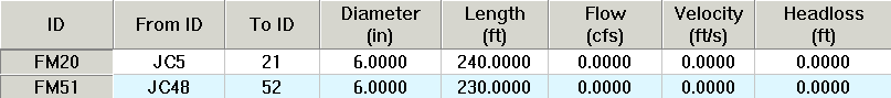
- ID - Force main identifier.
- From ID - ID of upstream node.
- To ID - ID of downstream node.
- Diameter - Inside pipe diameter, in (mm).
- Length - Pipe length, ft (m).
- Flow - The flow passing through the force main (as derived from the upstream pump), flow units. identifier.
- Velocity - The velocity of flow passing through the force main, flow units.
- Headloss - The total headloss experienced across the force main, ft (m).
![]()
EPS Pump Report
Shows extended period simulation results for all pumps in tabular format at a specified timestep. The report displays one record for each pump in the current project. Pump report columns include the Node Identifier, from ID, to ID, Flow, Head Increase, Usage and Pump Speed.
The following variables are displayed on the EPS Pump Report in the Output Report Manager for all or selected pumps:

- ID - Pump identifier.
- From ID - ID of upstream node.
- To ID - ID of downstream node.
- Flow - The flow rate passing through the pump, flow units.
- Head Increase - The hydraulic head increase the pump is lifting sewage flows, ft (m).
- Power - The power imparted by the pump, hp (kw)
- Usage - The number of pumps in the simulation.
- Speed – Pump Speed based on the pump affinity laws in the controls.
![]()
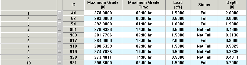
Range Loading Manhole Report
The Range Loading Manhole Report displays the maximum value of the load node grade (compared across the entire simulation period), and values of some other essential load node results corresponding to the time of occurrence of the maximum grade.
Ranges allow the user to see, in a report format, the maximum values experienced for any loading manhole in the system over the EPS. The reported variables include Maximum Grade, Maximum Grade Time, Load, Status, and Depth.
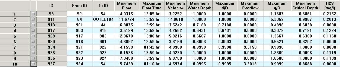
Range Gravity Main Report
The Range Gravity Main Report displays the maximum values for all pipes during the entire extended period simulation One record is displayed for each component of the selected component type.
Ranges allow the user to see, in a report format, the maximum values experienced for any gravity main in the system over the EPS. Gravity Main Reports include Maximum Flow, Maximum Flow Time, Maximum Velocity, Maximum Water Depth, Maximum d/D,Maximum Overflow, Maximum q/Q, Maximum Critical Depth, and maximum quality.
![]()